|
|
Control Objects
|

|
Think of a Control object as a "Controller" object, which
is typically a single circuit board residing in a PC or an
embedded system. A Control object manages that motion controller
board.
Every application creates a single Control object per board
(XMP controller).
A Control object can read and write device memory using I/O
port, memory-mapped or device driver methods. All communication
with motion controller firmware is handled by a Control object.
For the case where the application and the motion controller
device exist on two physically separate platforms connected
by a LAN or serial line, the application creates a client
Control object which communicates via remote procedure calls
with a server.
|
Objects taht are created with a
single Control
| Object |
Relationship to a Controller |
|
Adc
|
many-to-one,
must reside on that controller |
|
Axis
|
many-to-one |
|
Filter
|
one-to-one or many-to-one |
|
Motion
|
many-to-one or many-to-many |
|
Motor
|
many-to-one |
|
Recorder
|
one-to-one |
|
Sequence
|
many-to-one |
|
| |
|
Axis Object
|
 |
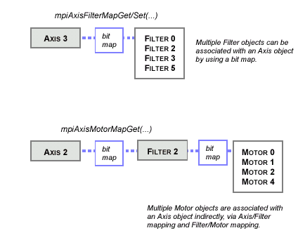
An Axis object is associated with a single physical axis
on a motion controller, and corresponds to a geometric axis
used for calculation of a path of motion. An Axis may be controlled
by one or more Motion objects.
The concept of an Axis is a "geometric" idea, but the main
purpose of an Axis object is to generate the desired path
(trajectory calculations, i.e., to generate command positions)
on every sample, using the path-planning data provided by
a Motion Supervisor. An Axis object is mostly a computational
block.
The Filter and Motor objects ensure that the command path
(calculated by Axis) is followed, and that the signals get
to the right motors.
|
Axis Objects Are Mapped to Filters and
Motors

|
|
|
|
Motion Objects
|
|

|
Think of a Motion object as really a "Motion Supervisor"
object.
The Motion (Supervisor) object corresponds to a coordinate
system or collection of axes. The primary function of the
Motion Supervisor is to provide data in a synchronized manner
to the Axis objects for use in path creation.
A second important function of the Motion Supervisor is to
monitor the status of all of the Axes under its control (and
all of the Motors, and Filters associated with these Axes),
so that motion can be stopped or resumed in a controlled manner,
especially in the event of errors. The Motion Supervisor is
the primary interface for a your MPI application with respect
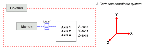
to motion. A Motion object maintains an ordered list of Axis
objects, which specify the coordinate system for all motions
to be performed with that Motion object. When a motion is
started, the type of motion is specified (trapezoidal, S-curve,
parabolic, etc.) along with type-specific motion parameters.
A Motion can be started directly (by calling a Motion method),
or started when the Motion is associated with a Command that
is called by a Sequence (that is executing). An Axis object
may be controlled by more than one Motion object, but only
one of those Motion objects may be active at a time.
|
|
|
|
|
|
Motor Objects
|

|
The Motor object corresponds to a physical motor used to
create motion. The primary function of the Motor object is
simply to provide an interface to the physical hardware associated
with the physical motor. The Motor object could practically
be called the "I/O" object (only the User I/O is handled outside
of the Motor object). Essentially, the Motor object is the
controller's interface to the outside world.
The data of the Motor object contains the state of encoders,
limit switches, home sensors, amplifier control and status
signals (amplifier enable, fault, step and direction), and
general purpose digital and analog I/O. Secondary functions
of the motor object include commutation control, limit checking,
and position capture and compare control.
To perform sinusoidal commutation, the Motor takes the outputs
from the Filter object. The Motor object also implements scale
interpolation.
|
|
|
| |
|
Filter Objects
|

|
The Filter object is concerned with the controller's control
loop, i.e., what should the controlled output be (usually
an input to a Dac) based on the position error? The Filter
is primarily a computational block, taking command positions
and actual positions and computing errors.
The Filter object calculates the output (usually the D/A
output level) that controlls a physical motor or motors, using
data (command positions) calculated by the Axis object. PID,
PIV and Biquad filter calculations are all parts of the Filter
object.
|
|
|
|
|
|
Event Objects
|

|
An Event object contains information about an asynchronous
event that has occurred. You typically obtain an Event object
from the EventMgr object.
|
| |
|
Notify Objects
|

|
A Notify object is used by a thread to wait for event notification.You
can configure a Notify object to wait and look for specific
events and for specific event sources.
|
| |
|
Event Manager (EventMgr) Objects
|

|
An EventMgr:
|
- obtains asynchronous events from the Control object(s)
that the EventMgr is associated with
- generates Event objects for enabled event sources
- awakens any threads that are waiting for events
|
|
|
| |
|
Recorder Objects
|

|
You typically use the Recorder object to periodically record
motion data. Note that you can only have one Recorder object
per Control object (controller).
|
|
|
| |
|
Sequence Objects
|

|
A motion application can issue individual motion commands,
or can create a series of motion commands (that are executed
in sequence by the controller). Essentially, you can use the
Sequence object to download commands that are executed by
the XMP controller, and not executed by the host.
Using the MPI, you can create a sequence of commands (a Sequence
object), using high-level motion (e.g., trapezoidal motion
profile on axes 2 & 4), using low level work (e.g., write
0x00043433 into memory address 0x2000).
A typical Sequence might be
|
- Start a motion
- Wait 60 msec
- Turn on a specific I/O bit
- Wait for motion to finish
- Wait for another I/O bit
- Start a new motion
|
|
|
| A Sequence object is always executed starting with the first
command. After completing the first command, subsequent commands
can initiate a new motion, set values in firmware memory, execute
a delay for a specified period, branch to a different command
in the sequence, wait for a condition to be met, and so on.
|
| |
|
Command Objects
|

|
A Command object specifies a single action that
is executed by a Sequence, such as motion, conditional branch,
computation, time delay, wait for condition, etc. Any Command
object that specifies motion must have a Motion object associated
with it. |
| |
|
Adc Objects
|

|
Adc objects manage the A/D converters on a controller (Control).
Typically the A/Ds can be programmed to perform conversions
on different channels. On every timer interrupt, the A/D performs
a single conversion, which takes 12 microseconds to complete.
A 16-Axis XMP controller has 8 A/D channels available for
your application's use. Each Adc can be correlated to a Motor
object.
Note: For the XMP, no more than 2 Adc objects can be
associated with a single Motor.
|
|
|
| |
|
Coordinate Systems
|

|
To create a coordinate system for a motion application, you
simply associate a list of Axis objects with a Motion object.
The list of Axis objects and the order of those Axis objects
on the list essentially define the coordinate system.
|
 |
|
|
|
|
|
|
|