| CHAPTER 5 XMP Controller MotionDrive I/O: Sercos | ||||||||||
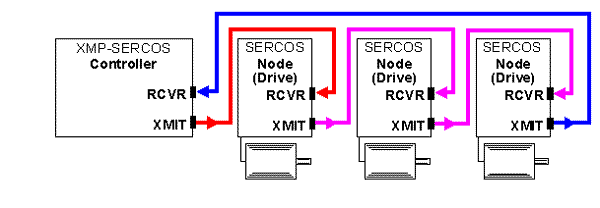
IntroductionSERCOS (SErial Real-time COmmunication System) is an optical networking standard for motion controllers and drives. It confers a number of advantages over electrically based, analog forms of control. Most notably, its fiber optic mode of communication reduces noise problems seen in electrical systems, while offering very high signal throughput. SERCOS devices are serially connected (i.e., "daisy-chained") in a ring configuration via "nodes," each node having its own dedicated receiving and transmitting ports. Data is sent in "telegrams," which contain either control or status information. These are sent by the controller (master) then received, processed, and relayed by each node (slave) in the ring. 
Normally configured XMP-SERCOS systems connect up to eight (8) nodes. An additional four nodes may be connected for a maximum total of twelve (12) nodes. This lends tremendous flexibility to SERCOS-based motion control systems. In the network example above, a single ring is featured with three separate drives, each having its own dedicated node. Almost any combination of nodes and drives is possible; however, the final configuration and number of drives within the system is limited by the required cycle time of each node and the controller. To determine the optimal SERCOS configuration for your motion control application, please contact Motion Engineering.
Besides parsing control data and sending feedback, each drive's on-board processor offers additional capabilities. Depending on the manufacturer, SERCOS drives have the ability to close a position, velocity, and/or torque loop, execute internal homing procedures, as well as latch position based on digital inputs.
Despite the fact that the XMP-SERCOS controller has a different physical interface than the standard XMP controller, the same MPI is used for both controllers. The complexity of the XMP-SERCOS controller's interface has been hidden by the MPI and by the firmware running on the XMP. The same development tools can be used for both controllers. The XMP-SERCOS controller requires an initialization procedure before telegrams can be sent to amplifiers. Once the initialization procedure has successfully executed, XMP-SERCOS controllers act the same as standard, analog XMP controllers. Design LimitationsDespite its many advantages, SERCOS does not confer "something for nothing." XMP-SERCOS controllers share some of the same limitations as analog controllers:
Controller-Drive CompatibilityDepending upon your choice of motion drives to be used with the XMP-SERCOS controller, you should consider some or all of the below parameters: Optical wavelength and power Motion
Engineering's XMP-SERCOS controller uses Agilent Technologies
HFBR-1505A/2505A transceivers for transmitting and receiving
data.1
TransmitterThe XMP-SERCOS controller transmitter , (HFBR-1505) incorporates an LED, transmitting at a nominal wavelength of 650 nm (± 10 nm). Optical peak output power (Pt) is software adjustable from -18.0 to -5.5 dBm. NOTE: power is affected by temperature: higher transmitter temperatures yield slightly decreased power. ReceiverThe Agilent HFBR-2505A receiver's peak input power varies from -20 dBm (Level Logic HIGH) to -42 dBm (Level Logic LOW). Data corruption may result if the receiver is overdriven (inputted optical power too high), or underdriven (inputted optical power too low). These conditions are discussed in the next section. Data Rate, Cycle Times and Configuring SERCOSThe number of devices capable of being operated by one XMP-SERCOS controller will depend upon the number and cycle times of drives and the number of networked nodes. It may prove advantageous to consolidate two or more drives into a lesser or greater number of nodes, depending upon the task(s) to be accomplished. To receive guidance on optimizing your SERCOS network, please contact Motion Engineering. 1. Agilent Technologies is a subsidiary of Hewlett-Packard. Data sheets for HFBR-1505A/2505A transceivers are available from Agilent via their web site: www.agilent.com. | |||||||||||