| CHAPTER 5 XMP Controller MotionDrive I/O: Sercos | ||||||||||
IDNsSIDNs and PIDNsIDNs, or Identification Numbers, are numbers identifying data that can be transmitted between SERCOS nodes and hosts. Design of a successful SERCOS network requires a thorough knowledge of all IDNs used.
There are two types of IDNs. SIDNs (standard IDNs) are defined by the SERCOS specification. These IDNs represent data that is commonly used in drive implementations. It should be noted that it is up to the manufacturer to decide which SIDNs it will support. PIDNs (product IDNs) are defined by the manufacturer. These IDNs represent data used in the drive for features not discussed in the SERCOS specification. PIDNs vary widely between drives and manufacturers. SERCOS Connection HardwareSERCOS CablingVariations in cable length and material have a profound influence upon power attenuation within networks:
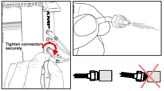
Specifications for SERCOS fiber-optic cable are found in Section 5.3.3 of the SERCOS interface standard (IEC 64191); however, network designers should consult their vendors for exact cable characteristics. Depending upon the cable material used (glass vs acrylic), length and bend radius, performance will vary. Section 5.3.5 of IEC 61491 specifies system data of the optical transmission path. Conforming cables must meet this specification. SERCOS ConnectorsXMP-SERCOS controllers utilize screw-on connectors having 1/4 - 36 UNS 2A threads. Typically, transceivers use molded plastic threads, while many cable connectors are steel; therefore, use caution to prevent cross-threading and stripping. 
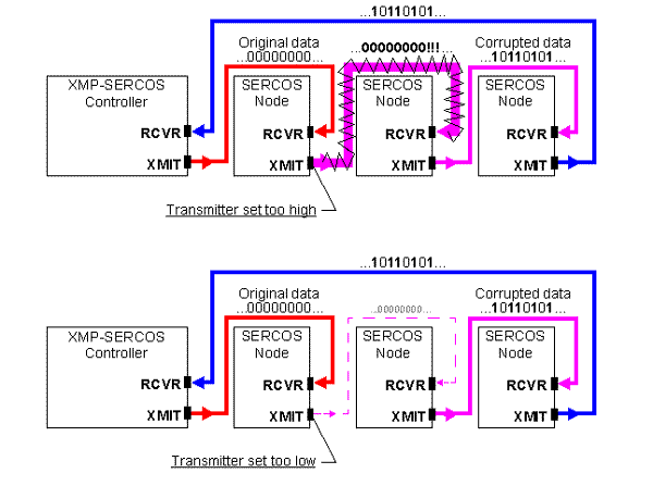
Loose connectors do not efficiently couple the fiber-optic cable's light energy to a transceiver and can cause data corruption. Under no circumstances should connectors be left loose. (This includes situations where a transceiver's power output is too high and can be reduced by loosening the connector; this is NOT a reliable way to adjust power output!) Setting Transmitter PowerAn integral part of building a SERCOS ring is establishing optimal transmitting power for each device in the ring. Starting at the XMP controller, an optical control signal is transmitted at a specified power level. The first device in the ring receives this signal, copies and processes it, then generates a new transmission. The next device in the ring receives this secondary transmission, processes it, and so on. This relay continues through every device until the controller becomes the last device in the ring. The controller processes the telegrams it has received, calculates new control commands, then transmits new telegrams during the next data cycle. The process repeats until halted by the controller, or an interruption in the ring causes a fault.
When building SERCOS networks, it is crucial to match the power of each device's transmitter with the downstream device's receiver. If power levels are set too low or too high, data corruption can quickly result--a common cause of errors and problems in SERCOS networks. 
| |||||||||||