| CHAPTER 3 Configuring An XMP-analog Motion Control System | |
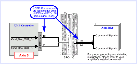
Connect to Analog Servo AmplifiersNOTE: Opto-Isolation of OutputsA number of controller outputs are optically isolated to protect both the controller and the drive amplifier, such as HOME LIMIT and AMP FAULT. The XMP's internal logic only controls current to the opto-transistor, thus presenting a "conducting" state between the collector and emitter (of the opto-transistor). Your external wiring determines whether an active low or an active high is presented at the input to your drive. | |
