| CHAPTER 3 Configuring An XMP-analog Motion Control System | |||
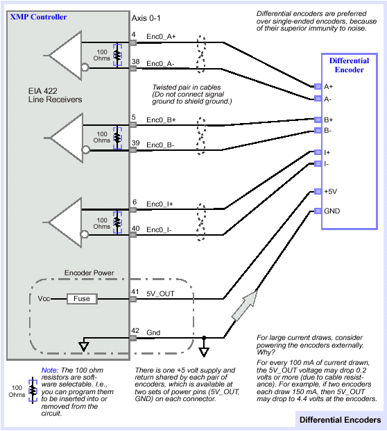
Connect to Digital Quadrature EncodersEncoder Wiring
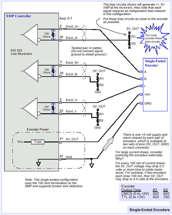
Connect to Single-ended EncodersBroken Wire and Illegal State DetectionThe encoder inputs (channel A+, A-, B+, B-) are monitored by the FPGA (an on-board logic component). The encoder inputs are sampled at 20mHz. By default, a digital filter is applied to each encoder input. This digital filter requires that an encoder input (channel A+, A-, B+, B-) be stable for 4 clock cycles (200 nanoseconds) before a transition is recognized, i.e., encoder input states lasting less than 4 clock cycles are filtered out. | |||