| CHAPTER
6 XMP Controller Motion Drive I/O |
|
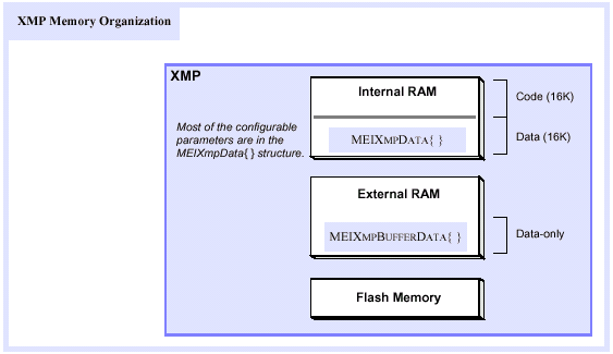
Memory OrganizationThe XMP has three memory regions: internal RAM (SRAM), external RAM (also SRAM), and flash memory. Internal RAM is split into two roughly equal sections of about 16K words (32-bit), one for code and the other for data. Another data-only region exists in external RAM. The MEIXmpData structure (defined in xmp.h) just about fills the internal RAM region. The MEIXmpBufferData structure is in the external memory region. (Almost all of the configurable parameters are in the MEIXmpData structure.) XMP memory organization.
Immediately after power-on or reset, the SHARC loads a small boot loader (~128 words) from the bottom of flash memory into internal RAM, and then branches to the first instruction. This boot loader then loads the rest of the firmware code (~16K words) from the same flash memory page and then jumps to the first firmware instruction. The firmware then copies data into the MEIXmpData (internal RAM) and MEIXmpBufferData (external RAM) structures from identical copies stored in flash memory. Corrupted Flash Memory?It is very difficult (but not impossible) to corrupt the flash memory, because there are software and hardware locks which make this improbable. If you suspect that the flash memory is being corrupted, make sure that all of your software developers know who is writing updated values to flash memory and when they are doing that. Often, one member of your software developer team is writing updated values to flash, and forgetting to tell the other team members about it. |
|
