| CHAPTER 6 XMP Controller Motion Drive I/O |
|
XMP Data ArchitectureThis section provides a dynamic look at the XMP's data architecture, between board components, and between the controller and external devices such as drive amplifiers. XMP Power-up SequenceWhen first powering-up the XMP controller, several actions initialize the controller according to the firmware's settings and prepare it for motion control. Power is appliedDuring power-up, the host computer initializes. Power is also supplied via bus lines to the XMP controller and other devices connected to the PCI bus. The XMP controller's power supervisor waits for the bussed power supply to attain voltage thresholds (2.93 for 3.3 VDC power, and 4.63 for 5 VDC power) before powering the controller's components. Until power fully stabilizes, the board is kept in a reset condition. 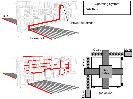
Once initialized, the CPU bios polls the bus and assigns an address to each device (including the XMP controller). 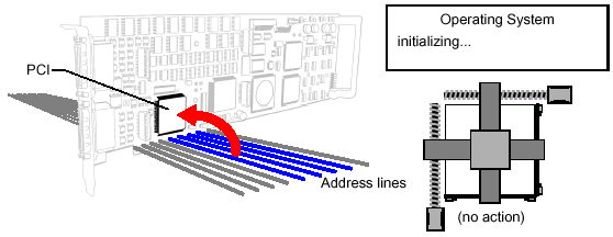
PCI handshakes with SHARC DSP and LatticeWhen the XMP controller's PCI receives a bus address from the host computer's CPU bios, it handshakes with the SHARC and Lattice. 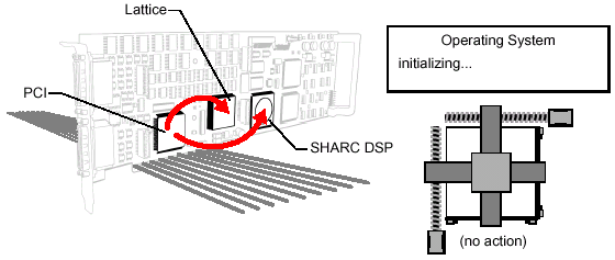
FPGAs loadedWith the FPGA's file format determined, the SHARC loads both FPGAs with the following:
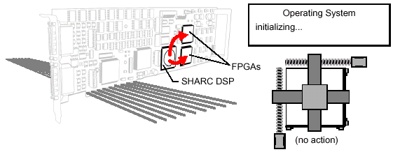
Firmware loaded from flash memory into the DSPWith the FPGAs loaded, the controller is now ready to load the firmware from flash memory to the DSP. 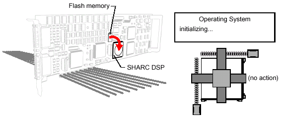
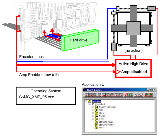
DACs calibrated and activatedAt the beginning of the power-up process, the digital-to-analog converters (DACs) are kept grounded (i.e., in an inactive, OFF state) until the controller is ready to switch them in. This avoids erroneous inputs-outputs with the drive. After the DSP is loaded, the DACs are internally calibrated and activated. The system may now accept input from the drives and send commands. 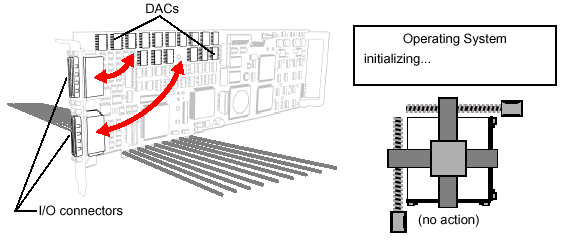
Controller initializesThe controller's boot configuration is based upon parameters stored in flash memory; these determine the controller's (and drive's) start-up behavior. One of the programmer's first tasks is to define what this "hello world" starting state ought to be immediately after power-up. In some instances, it may prove advantageous to keep a default boot configuration in flash memory, then modify it from the application during boot-up. In other instances, it may be better for the application to flash the controller's memory with an entirely new set of parameters during boot-up. The user must determine the best approach.
Controller configuration can be done using Motion Console; however, during development of an application, it is the programmer's responsibility to write code that properly configures the controller for its next session upon exit of the application. The controller should utilize safe amp enabling and hardware I/O to prevent runaway conditions during start-up.
For this example, we will assume the following safety measures:
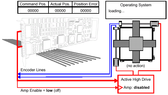
Device Driver and Operating System LoadsAt this point, the XMP controller is initialized and ready for use. The next and final phase of the power-up sequence is the loading of the XMP's device driver and operating system on the host computer. This must be completed before any motion control application can be loaded and run. 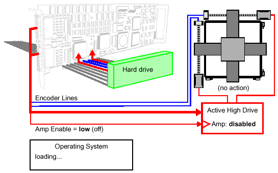
The XMP controller's device driver is shipped to load manually; however, it can be reconfigured to load automatically. To view the XMP's device driver, access your operating system's Devices window. (In WindowsNT? environments, the XMP controller's device driver is labeled as MeiXMP.) 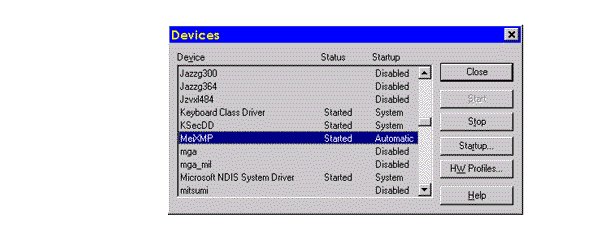
The operating system completes its loading within several seconds of the XMP's initialization. Create Control Object and Initialize ControllerBefore any motion application can move axes, it must create a controller object and initialize communication. This is a standard requirement for any application which intends movement. 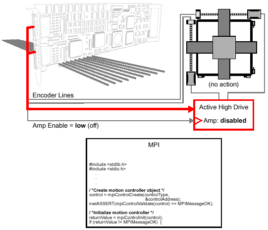
Homing the Motion Control SystemHoming is the setting of a coordinate system through detection of a known point in space (the "home" point). A home point can be defined using a limit switch, or by detecting a signal from the encoder such as a home or index pulse. This is typically the first act a controller must perform before running the main application code.
Before homing, objects must be created and the controller must be initialized (see above). One example of a homing sequence is shown below, consisting of:
This homing example is taken from the home1.c sample application program, which may be found in the Sample Applications module and should be studied. For sake of clarity, excerpts are included below. Configure the Capture triggerAfter the motion objects are created and the controller is initialized, the MPI must configure and arm a capture. The trigger in this example is a home sensor (limit switch) on a stage. 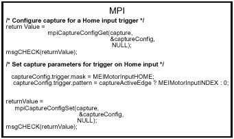
Define motion parametersIn preparation for commanding moves, there are several motion parameters which must be defined:. 
Two types of moves are used for this sample homing routine: a velocity move and a trapezoidal move. The velocity move consists simply of running the axis at a set velocity, hunting for the home point, without regard to its starting and ending positions.
Because a trapezoidal move requires beginning and ending positions (and we don't know the axis coordinates until the home point is detected), the first move must be a velocity move. After coordinates are established through detection of a home point, a trapezoidal move may be used to move the axis to the origin. Configure the home event actionThe "home event" is the what we use to detect the home point. The home event could be an input from a limit switch, triggered when the axis runs into it. The home event could be a home or index pulse on the encoder. For this example, the stage's HOME switch is used as the trigger, and the trigger's input is configured to be TRUE (active edge).
The "home action" is what happens when the home is detected. In this example, the programmer has decided to define the action as a command to STOP the axis. 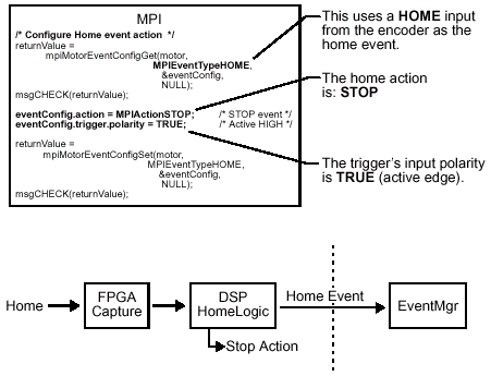
Arm the triggerWith the home event and action defined, all that is left is to "arm" the trigger by setting the mpiCaptureArm to TRUE. Recall that earlier, this was set to FALSE to "disarm" the system. 
Start a velocity moveWith the capture event and action defined, and the trigger armed, we are ready to hunt for the home point. This is accomplished by commanding a velocity move. Before the axis can be commanded, however, the XMP controller must first enable the drive. In this example, it is assumed that the drive is wired to be an active high type; therefore, the Amp Enable line is set to high (on). Drive enabling via software must be done as a separate code item and is not shown here: 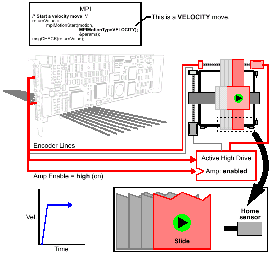
As the leadscrew rotates, the slide approaches the home sensor. Poll trigger statusWith the trigger armed, the software's next task is to poll the status of the trigger while the axis continues rotating. 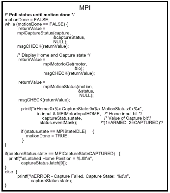
Home event detectedAs the axis motor continues turning, the leadscrew rotates until the stage makes contact with the home sensor; this acts as the trigger. When the trigger event is detected, the encoder position is captured and a stop action is initiated. 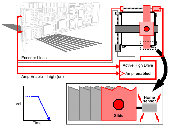
Define the home position as the originWhen the home pulse is detected in our example, another simultaneous action is initiated: the axis's position is captured by the FPGA. At this point, the axis position is recorded in memory. Meanwhile, the axis slows to a stop. The mpiAxisOriginSet command is then used to set the capture position to zero, making it the new origin of the axis's coordinate system. 
Move axis to the (new) originOur sample homing routine's last task is to move the axis to the origin. Recall that the home pulse was detected while in motion, and that after detection, the axis coasted to a stop. This means that the axis is now somewhere beyond the home point (our new origin).
Because we now have a coordinate system, we can perform a backward trapezoidal move from the current position to the intended position (the origin). 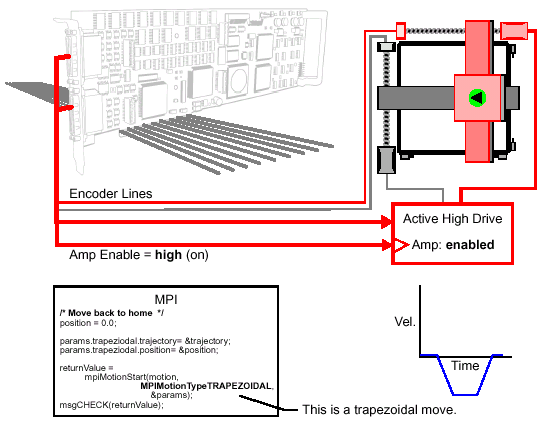
Delete Objects Finally,
the homing routine must delete the objects it has created.
This is performed with a number of deletion objects such as
mpiMotionDelete, Internal Data Movement via "Riptide"Within a typical SHARC timer cycle, data is moved back and forth between the SHARC and the FPGAs and various feedback devices (e.g., encoders, resolvers, etc.). On the XMP controller, this is performed over a proprietary, dedicated data bus called the "Riptide." The Riptide is the serial backbone of all motion data flow. Within a given SHARC cycle, data moves first from the SHARC to the FPGAs, and then to the drives. Within the same cycle, data is moved in the opposite direction (inbound) from the drive and encoder(s) to the SHARC. 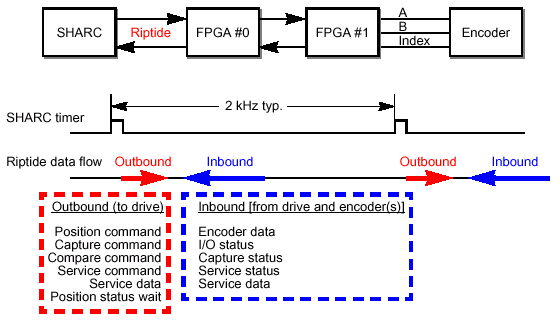
As more drives and encoders are added to the motion control system, the required data bandwidth increases across the Riptide, occupying a greater portion of the foreground tasks. 
| |
