| CHAPTER
6 XMP Controller Motion Drive I/O |
|
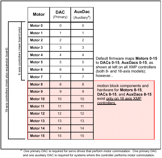
Digital-to-Analog Converter (DAC) SubsystemThe command link from the XMP controller to analog input servo drive is the DAC. (In contrast, stepper drives receive commands from the XMP controller via transceivers; DACs are not used for steppers.) The XMP controller can have up to two DACs per axis. DACs are separated into primary and auxiliary DACs. One channel is used for standard servo control ("primary") and the other channel is an auxiliary, OR both channels are used for sinusoidal commutation.
Using the firmware's default settings, motors are mapped to DACs according to the table below. The firmware provides for a fully configured, 16-motor controller (consisting of a linked main and expansion board) by mapping all 16 motors to 32 DACs (16 primary, plus 16 auxiliary). If a controller consists only of one main board (8 motors), the expansion hardware to support the additional motor-DAC mappings (motors 8-15, DACs 8-15, and AuxDacs 8-15) does not exist, and the firmware ignores them. |
|