| CHAPTER 2 Motion Console |
|||||||||
Safety RemindersAs you map out your motion control system using the Object Explorer, you must address specific safety factors. These should be addressed BEFORE you mechanically engage motors to axes, and connect motion hardware to the controller. Establish a Safety ZoneIf you have not already done so, define a safety zone around the motion system to be configured. Areas traversed by hardware should be clearly marked and/or partitioned to keep out personnel, hands, fingers, etc. Warning signs and labels should be clearly posted. Mount an Emergency Off SwitchAt least one emergency off (EMO) switch should be prominently mounted where operators and technicians can easily locate and reach it at all times. Depending upon your system, the EMO should effect a rapid and safe stop of all components, preferably wired through the power lines of the system components themselves. Consider using automatic mechanical braking where heavy and/or fast components might coast dangerously after the loss of a controller. Wire all Drive Amplifiers for Fail Safe OperationThe wiring of your system's drive amplifiers is a critical design detail and is discussed in the XMP Hardware Installation Manual. As part of your design, you must decide whether to wire the drive's amplifier enable (Amp En) line as "active high" or "active low." Regardless of the method used, ensure that your motion system cannot run away when power to the controller is lost. Design for the worst possible power loss scenario, then ask yourself: "Is this machine safe with power to the controller turned off?" Amplifier enabling should be tested in crude hardware fashion before the system is either mechanically coupled or connected to an XMP controller. Once hardware wiring has been tested for fail-safe design, proceed to the configuration of Motor Summary / General Configuration attributes (see below). Configure Motor Summary / General Configuration Attributes Attributes
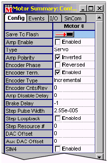
in the Motor Summary / Config tab page configure
both motors and encoders. Of particular import to safety are
the following:
Each
of these attributes are described in a separate section of this
chapter. The Amp Enable and Polarity attributes
are treated in the XMP Hardware Installation Manual.
Note especially that once a motor's Amp Enable line has
been wired, the Amp Enable and Polarity attributes
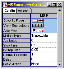
must accord with system wiring to avoid problems. Encoder Phase and Encoder Cnts/Rev affect the safety of your system by telling the controller which way an axis is moving, how far and how fast. If encoder attributes are set wrong, you may experience runaway problems. Configure Motion Supervisor Summary / General Configuration AttributesAttributes in the Motion Supervisor Summary / Config tab page include those used to configure a motion system's panic actions. These tell the controller what to do when an error or panic stop command is encountered. If they are not correctly configured, your controller may ignore an operator's command to stop! Attributes include the following:
The Panic Action parameter is of particular importance. When switched to None, the controller will take no action after panic events! Please note that the <F12> panic stop key generates a panic action for all Motion Supervisors, according to how Panic Action is configured. | |||||||||

