| CHAPTER 2 Motion Console |
|||||||||||||
|
|||||||||||||
| actual state depends on Amp Polarity and wiring. See the XMP Hardware Installation Manual for more information. |
(not enabled)-- Disable amplifier.
| enable state depends on Amp Polarity and wiring. See the XMP Hardware Installation Manual for more information. |
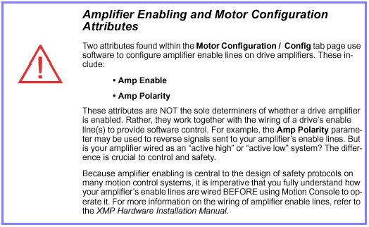
Inverted--
Amplifier enabled when output signal is high.
| this is dependent upon external wiring. See the XMP Hardware Installation Manual for more information. |
(not inverted)-- Amplifier enabled when output signal is low.
| this is dependent upon external wiring. See the XMP Hardware Installation Manual for more information. |
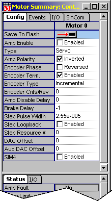
Encoder Phase-- Determines which direction of motor movement results in incrementing or decrementing encoder counts. It is very important to use the correct encoder phasing so that positive voltage will result in increasing counts and vice-versa.
| Note | phasing can also be reversed by reconfiguring the A+/- and B+/- encoder wires, e.g., swapping the A+ and A- wires. |
(not reversed)-- Encoder phasing is passed to the controller directly, as wired.
Reversed-- Inverts direction of actual position traveled for given encoder feedback.
Enabled-- Enables 100 Ω resistor between complimentary encoder signals. Use this setting for XMP controllers without SIM4 modules.
(not enabled)-- Disables 100 Ω resistor between complimentary encoder signals. Use this setting for XMP controllers with SIM4 modules, using analog interpolated feedback.
Incremental-- Standard incremental-type encoders. No absolute position information stored.
ABS 0-- Configures encoder feedback for absolute encoders. Not all absolute encoders are supported; please contact MEI.
- Encoder Cnts/Rev-- (Used with ABS 0 above.) Encoder counts per revolution. Used primarily for sinusoidal commutation.
- Amp Disable Delay-- Delay (in seconds) before disabling amplifier on events that cause an Abort.
- Brake Delay-- (Unsupported.)
- Step Pulse Width-- Sets the width of a step pulse. (Range: 50 ns to 1.6 ms)
- Step Loopback-- (Used with stepper motors only.) Loops back the step output pulses into the encoder inputs to simulate feedback.
Enabled-- Uses step output to determine IN.POSITION and ACTUAL.POSITION. (Correct choice for stepper systems to prevent unwanted error limit events.)
(not enabled)-- Requires feedback device for ACTUAL POSITION, Error Limit, etc. (Should be selected for non-stepper systems.)
- Step Resource # -- Reflects which motor block the motor is associated with. This parameter is only useful for XMP-Pulse controllers. All other XMP controllers should set the Step Resource Number equal to the Motor number.
-
For XMP-Pulse users -- the Step Resource Number can be used to share the resources of a single motor block between two stepper motors. This is useful when you have more motors than motor blocks. You can remap a motor so that it will share resources with another motor block by setting the ResourceNumber to the appropriate Motor Block number. Each motor block can have up to two stepper motors mapped to it. The Step Resource Number reflects which motor block a stepper motor is mapped to. For more infomation, see the XMP-Pulse Appliction Note 218.
- DAC Offset-- Adds an offset value to the Motor's DAC Output signal. Valid values are +10V through -10V.
- AUX DAC Offset-- Adds an offset value to the Motor's Auxiliary DAC Output signal. Valid values are +10V through -10V.
- SIM4-- Scale Interpolation Module. For more information regarding the SIM4 module, refer to Application Note 206, available from MEI.
(not enabled)-- Not using SIM4 module.
Configuration Attributes: "Events" Tab Page
The generation of Motor events is based upon the Motor configuration attributes.
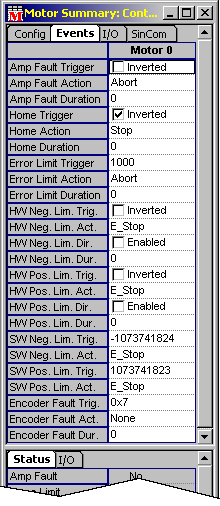
Motor events are state changes in the motor object that can be programmed to trigger a particular action. The status of motor events can be monitored in the Event Status page of the Motor Summary window. Motor events are passed up to the Motion Supervisor object (via Filter and Axis objects) and can be monitored as event status flags on the Status tab page on the Motion Supervisor Summary window. If action is taken when the event is triggered, then the event status flag is "sticky," i.e., stays on until explicitly cleared by the user. This allows the user to determine which motor(s) caused an error. Events have some or all of the below configurable attributes.
Triggers
Triggers listed on the Motor Summary / Events tab page include:
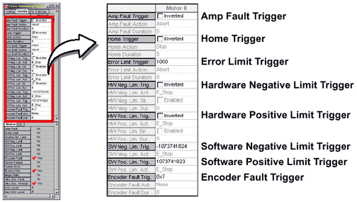
Triggers can be a state change (e.g., Amp Fault Trigger or Hardware Negative Limit Trigger) or positional information (e.g., Error Limit Trigger).
Inverted-- I/O polarity is inverted.
(not
inverted)-- Condition triggers event.
Actions
Actions listed on the Motor Summary / Events tab page include:
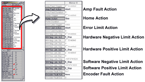
Actions are taken when an event is triggered (see "Triggers" section above). In all cases, the following acions are available:
None-- No action taken. The event status will be flagged only while the condition of the event is met. For all other actions, the event status is "sticky."
Stop-- Stop the motor within the Stop Time defined in the Motion Supervisor / General Config tab page associated with the motion of this motor. There is no effect on the state of the axis (axes) or Motion Supervisor(s) associated with the motor. The event status is "sticky," but it will clear the next time motion is commanded.
E-Stop-- Stop the motor within the E-Stop Time defined in the Motion Supervisor / General Config tab page associated with the motion of this motor. The Axis (or Axes) and Motion Supervisor(s) associated with the motor will be left in an error state.
E-Stop, Abort-- Same as E-Stop action (above), except that the motor amplifier is disabled after the motor stops. An additional delay can be defined by setting the Amp Disable Delay attribute on the Motor Summary / General Config tab page.
Abort-- Disable the motor amplifier. A delay can be inserted before disabling the amplifier by setting the Amp Disable Delay attribute on the Motor Summary / General Config tab page.
Duration
Minimum amount of time, in seconds, that the Trigger condition must exist for the event to trigger.
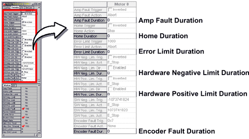
Direction
The Direction attribute, when Enabled, characterizes the Hardware Negative or Positive Limit Trigger directionally.
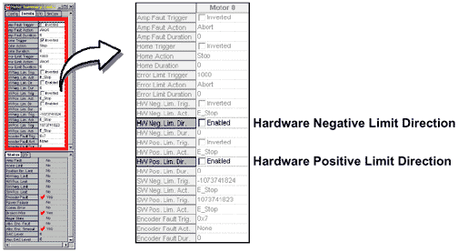
When not enabled, the event will always be triggered, even when the motor is not in motion. When enabled, both hardware and software limit events are triggered when the motor is commanded to move only in the Direction the limit is associated with.
Configuration Attributes: "I/O" Tab Page
Tranceiver
(XCVR) configurations are controlled from the Motor Summary
/
I/O tab page. Input-output status can be monitored by viewing
the I/O status page at the bottom of the window.
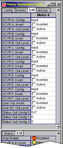
Input-- XCVR configured to receive an input signal.
Output-- XCVR configured to send an output signal.
Step-- XCVR configured for step mode. (XCVR A and B only.)
Dir[ection]--
XCVR configured for direction mode.
(XCVR A and B only.)
CW-- Clockwise. (XCVR A and B only.)
CCW-- Counterclockwise. (XCVR A and B only.)
Quad
A-- Standard quadrature operation (A).
(XCVR A and B only.)
Quad
B-- Standard quadrature operation (B).
(XCVR A and B only.)
- XCVR A[B, C] Invert-- Inverts the polarity of XCVR configured for Output (incl. step, etc.) if Inverted is selected.
- XCVR A[B, C] Out Level-- Active or (not active).
- User Out: Invert-- Inverts the polarity of output bit (Inverted), or normal.
- User I/O: Out Level-- When Active, internal logic sets bit level to high.
Configuration Attributes: "SinCom" Tab Page
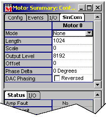
Closed Loop Mode-- Commutated, closed loop.
Open Loop Mode-- Commutated, open loop.
Simulate-- Sets the motor commutation mode to MEIXmpCommModeSIMULATE.
- Length-- Number of encoder counts per revolution for a rotary motor and the number of counts of one electrical cycle length for a linear motor.
- Scale-- (Type float) Total number of commutation points per motor revolution, divided by the total number of encoder counts per revolution (i.e., Length).

- Output Level-- Sets the DAC level during open-loop commutation. Output level is in DAC units (i.e., 32,767 = 10V).
- Offset-- Expressed in units of commutation table points (i.e., 1024). 1024 table points equal 360 electrical degrees.
- Phase
Delta-- Usually set to 120 degrees for a three-phase,
brushless motor with 120 degrees of phase separation. [120
degrees is represented by 341 commutation table points (i.e.,
1024/3).] Switchable options include: 0 degrees; 90 degrees;
120 degrees.
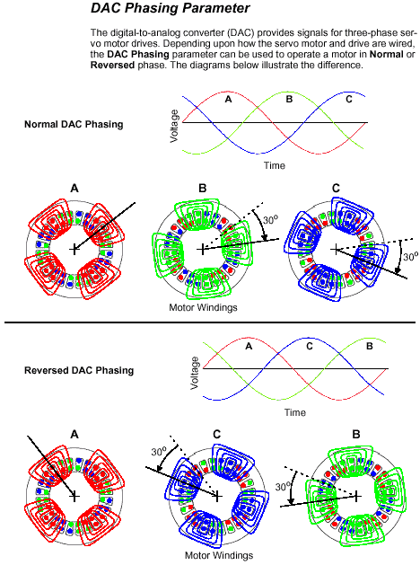
90 degrees is normally reserved for a two- or four-phase motor. - DAC Phasing-- Sets phasing of three-phase motors.
(Normal)-- Phasing is unaltered.
Reversed-- Phasing is reversed 120 degrees.
Status Attributes: "Status" Tab Page
This page displays the status of motor events, as well as several general stats flags. DAC output level is also displayed.
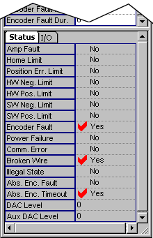
- Amp Fault-- Amp Fault Event status
- Home Limit-- Home Limit Event status
- Position Err Limit-- Position Error Limit Event status
- HW Neg. Limit-- Hardware Negative Limit Event status
- HW Pos. Limit-- Hardware Positive Limit Event status
- SW Neg. Limit -- Software Negative Limit Event status
- SW Pos. Limit-- Software Positive Limit Event status
- Power Failure-- Power Failure Event status
- Comm. Error-- Communication Error status flag
- Illegal State -- Illegal State status flag
- Abs. Enc. Fault -- Absolute Encoder Fault status flag
- DAC Level-- DAC output level in volts
- Aux DAC Level -- Auxiliary DAC output level in volts
Status Attributes: "I/O" Tab Page
This page displays Motor I/O status.
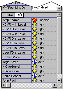
- Amp Enable-- Amp Enable output status
- XCVR A In Level-- Transceiver A input level
- XCVR B In Level-- Transceiver B input level
- XCVR C In Level-- Transceiver C input level
- XCVR D In Level-- Transceiver D input level
- XCVR E In Level -- Transceiver E input level
- XCVR F In Level-- Transceiver F input level
- User I/O In Level-- User I/O input level
- Broken Wire -- Broken Wire input level
- Illegal State -- Illegal State input level
- + Overtravel-- Positive Limit input level
- - Overtravel-- Negative Limit input level
- Home Sensor-- Home Limit input level
- Amp Fault-- Amp Fault input level
