| CHAPTER 3 Motion Scope | |||||||
Traces"Traces" refer to the actual signal data plot(s) generated on a display pane. The Traces menu item may be selected either by clicking on Pane / Traces in the pull-down menu, or by clicking on the Traces button on the main display. This displays the Select Traces Set panel: 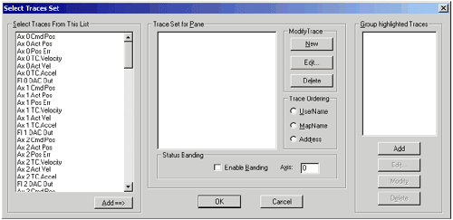
On the left side of the panel are listed some of the possible signal data which can be traced. They are selected by clicking with the mouse, then clicking on the Add==> button below. 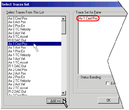
Click on the signal data to be traced , then on the Add==> button . The signal data will be added to the Trace Set for Pane list.
Trace Ordering-- Once a list is defined in the "Trace Set for Pane" window, you may order the arrangement by using the Trace Ordering switch. There are three menu items: UserName-- Orders the list by user name. MapName-- Orders the list by map name. Address-- Orders the list by memory address (as ordered within the controller's firmware memory). TIP: click this menu item again to reverse the order. 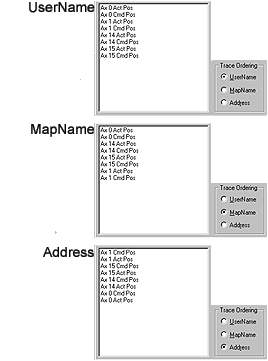
Trace Ordering menu items arrange signal data on the Trace Set for Pane window by user name, map name, or memory address.Modify Trace menu items create, edit and close individual traces. These menu items are accessed on the right side of the Select Traces Set panel: 
New and Edit-- Clicking on either the New or Edit button displays the Edit Trace Properties panel. If no trace is currently listed or selected within the "Trace Set for Pane" window, only the New button may be used. 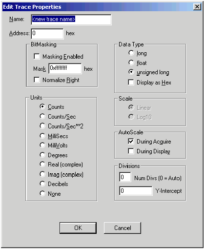
Name-- Name assigned to the new or edited trace. Trace names can be assigned to correlate to specific axes, such as "X," "Y," etc. Address--
Hexadecimal memory address to be assigned to the selected
trace.
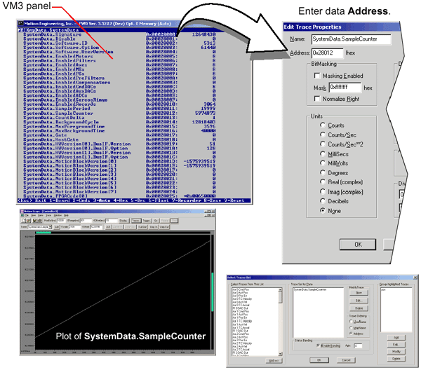
Plot of SystemData.SampleCounter data.Bitmasking-- Allows bitmasking of current trace address. The following fields are used: Masking Enabled-- When enabled, the data is masked. Mask-- Bit pattern to be masked (bitwise ANDed with mask). Normalize Right-- If a Mask has zeros in its lower-order bit(s), the data value is shifted to the right. This is especially convenient for viewing binary, two-state values. Data type-- Specifies the data type of the value stored at the Address. The following data types are selectable: long-- Data is a long integer (32 bits). float-- Data is a floating decimal point value (32 bits). unsigned long-- Data is an unsigned, long integer (32 bits). Display as hex-- When selected, data stored at the Address is displayed in hexadecimal form. If not selected, data stored at the Address is displayed in its default format. Units-- Units applied to the vertical (Y) axis of the display pane. The following units are selectable: Counts/sec-- Encoder counts per second. None-- No units are applied to the vertical axis. OK-- Enters settings and closes the Edit Trace Properties panel. Cancel-- Closes the Edit Trace Properties panel without changing settings.
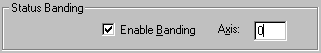
The Status Banding menu item within the "Select Traces Set" panel turns on-off separate trace bands at the top of the pane for monitoring IN_COARSE and IN_FINE status on a single axis. Two color schemes are used: green = FALSE; red = TRUE. 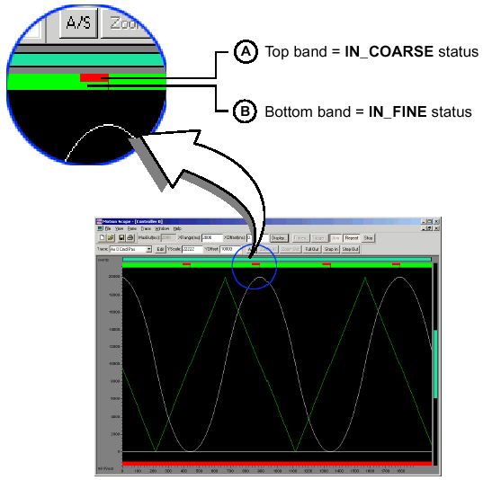
Trace showing use of Status Banding menu items. In
above, the Status Banding menu item has been enabled
for the axis indicated by the Axis field. Command velocity
(trapezoidal profile) reveals motor movement. As the command
position (curved profile) crosses the IN_COARSE position value
at
| |||||||
 , the
IN_COARSE band (topmost band) changes color from green-FALSE,
to red-TRUE. (Meaning, the position of the axis is now within
the IN_COARSE envelope of the target position.) As the axis
reaches the target position, it enters the IN_FINE envelope
at
, the
IN_COARSE band (topmost band) changes color from green-FALSE,
to red-TRUE. (Meaning, the position of the axis is now within
the IN_COARSE envelope of the target position.) As the axis
reaches the target position, it enters the IN_FINE envelope
at  , and
the lower (IN_FINE) status band changes color from green-FALSE,
to red-TRUE.
, and
the lower (IN_FINE) status band changes color from green-FALSE,
to red-TRUE.